For More Information, Please Contact
Direct ManufacturerOriginal Price
Full certificates, acceptance testing upon factory release.
Contact to order: Hotline/Zalo: 0936 629 323
What is the definition of HL93 load?
What is HL93 load
What does the concept of HL93 load represent?
You may not know this, before buying a load-bearing product such as a manhole cover or drain grate for installation in a construction project. And sometimes you may have heard the term HL93. So what does it represent? The answer will be in this article.
Concept of HL93 load What is the HL93 load standard?
HL93: Highway Load accepted in 1993
(Highway load accepted in 1993)
In 1993, the moving load model was replaced to better suit the traffic situation of heavy truck types. A new load model was adopted by AASHTO and named “Highway Load’93” or HL93, and HL93 does not represent any specific type of vehicle. It meets the criteria for safety with a larger, but more frequent, load class than allowed.

The history of formation and improvement of the HL93 load is as follows.
Precast manufacturers producing underground products such as box culverts and pump chambers have for years designed their products for AASHTO HS20-44 or Alternate Military Load (Interstate Load), whichever creates the worst condition on the structure. They are beginning to see specifications for projects requiring AASHTO HL93 truck loading. How will the new load specifications affect future designs for underground structures currently based on the requirements of the old load specifications?
The American Association of State Highway and Transportation Officials (AASHTO) was formed in 1914 to provide guidelines for the design of structures within highway rights-of-way. The State Department compiled and created the necessary specifications. The document is titled "Standard Specifications for Highway Bridges". For many years it has defined the load and design requirements for precast (or cast-in-place) concrete structures. Recommendations from this document are included in the ASTM specifications written for underground precast concrete structures such as C478, C890, C913, C1443, and C1557.
The most recent edition of the Standard Specifications for Highway Bridges was the 17th edition, published in 2002. The design methods in these 17 editions included Allowable Stress Design (ASD) and Load Factor Design (LFD).
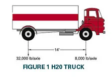
The first truck loading used had the designation H20 (see Figure 1), covering a two-axle truck weighing 20 tons. The front axle carried 8,000 pounds and the rear axle, 14 feet away, carried 32,000 pounds. The 1944 edition included the HS20 truck loading and began the policy of attaching the year to the load making HS20-44 the official designation. The additional ‘S’ provided an allowance for the heavier tractor-trailers available at the time.
Figure 2 depicts the load spacing and loads for the HS20-44.
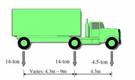
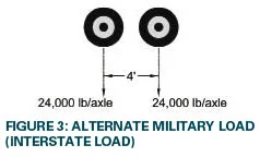
When the Federal Highway System developed in the 1950s, one of its goals was to transport military vehicles. Alternate Military Loads (also known as Interstate Loads) were created to cover the axle loads from heavy military equipment. This new load, shown in Figure 3, consists of two axles 4 feet apart with each axle carrying a load of 24,000 pounds.
A lane load system was created to provide a simpler method of calculating moments and shear than using concentrated wheel loads as in Figures 1 and 2. Lane loads were used in the designs of bridge decks spanning multiple lanes over multiple spans. They were not used to design structures below grade, because concrete boxes typically consist of relatively short single spans when compared to bridge spans.
There was some concern in the late 20th century that the HS20 truck load did not fully reflect actual conditions. Therefore, some engineers requested the HS25 truck load, for underground precast structures. This rating was understood to be 25% higher than the HS20 truck load. Thus, the HS20 axle load of 32,000 pounds became the HS25 axle load of 40,000 pounds. The increased loading in some cases could create the need for additional steel reinforcement and sometimes a thicker top slab on underground structures installed in areas exposed to heavy truck loads.
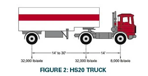
The HL93 designation includes a design truck plus the design lane load or a tandem design plus the design lane load, whichever creates the worst case. The design truck is identical to the HS20 load configuration shown in Figure 2. The design tandem is the same as in Figure 3 except the axle load is 25,000 pounds instead of 24,000 pounds. The term LARGER lane load is new and applies to the design of the bridge deck above. It does not apply to structures below grade. This is confirmed in the ASTM C1577 standard, which states that the tables are created using AASHTO HL 93 live load without the lane load as AASHTO allows.
Many manhole cover manufacturers ask the question, how does the new HL93 load affect the design of structures that were designed with the wheel loads specified in the old document "Standard Specifications for Highway Bridges"? The covers are small enough that only one wheel can be on top of the structure at any time. The wheel load is half the axle load.
An old versus new comparison indicates that the difference is very small. The wheel load in the HL93 design truck is the same as the HS20 wheel load. The HL93 design tandem wheel load is 12,500 pounds compared to the 12,000 pound alternate military load. The additional 500 pound wheel load is not a major increase and will only affect designs that do not have excess capacity.
Designs based on the HS25 load may in some cases be capable of carrying the new design truck load. The 20,000 pound wheel load for the HS25 is greater than the 16,000 pound design wheel load of the Truck in HL93.
The wheel load affects the top slab design more than the wall and bottom slabs. This is especially true when the slab is under 2 feet of cover. The effect of the wheel load on the slab decreases as the depth of cover increases. The wall design will in the vast majority of cases not be affected by the small increase in loading required by the LRFD Bridge Design Specification. The same is true for the bottom slab design.
It can be concluded that the new load may affect existing designs, but the difference between old and new does not mean that all designs need to be updated. The small increase will not affect designs that have excess capacity. Those designs that minimized reinforcement and slab thickness to create a just-good-enough structure may need to be reviewed.
These conclusions are based on a wheel load comparison and do not include the many other factors used in design. Items such as impact, depth of cover, load and resistance factors all play a part in the final design. A true comparison of the designs must be made based on the criteria used in the predecessor’s previous calculations.
A comparison of two ASTM specifications demonstrates that the old designs are not inferior to the new designs using LRFD. ASTM C1433 was written for box culverts using the old load factor design (LFD), while ASTM C1577 was written for box culverts using the newer LRFD design. Some steel areas required in the newer specifications are less than the steel areas required in the older specifications. This comparison confirms that the new HL93 load is not meant to cause redesign of underground precast structures.
General conclusion:
The bridge live load model specified in the AASHTO LRFD code has been developed over the years to account for changes in vehicles, advances in modeling techniques, and new and better data on existing traffic. As traffic continues to evolve, FHWA is revisiting this issue as both timely and appropriate. Preliminary data suggests that changes may be required and confirms the efforts involved in the studies.
References
Kulicki, John & Stuffle, Timothy. Final Report: Development of AASHTO Vehicle Live Load. Submitted to the Federal Highway Administration on December 18, 2006.
Kulicki, John & Mertz, Dennis. The Evolution of Vehicular Live Load Models in the Interstate Design Era and Beyond. July 11, 2006.
AASHTO LRFD Bridge Design Specifications, 6th Edition. 2012.
Leech, Thomas & Kaplan, Linda. The Bridges… Pittsburgh at the Point… A Journey through History. Copyright 2016. Woodridge Publications, LLC. Word Association Publishers, Pittsburgh, PA.
WIM data provided by the Intelligent Infrastructure System, Philadelphia, PA 2019.